Each Hill Hiker® lift system is custom designed and built by hand in the USA to the exact characteristics of each customers’ hillside: including adherence to local and national building codes and desired options and capabilities.
Design | Manufacture | Install | Service
Hill Hiker, Inc. prides itself on its manufacturing and installation processes which DELIVERS the highest quality hillside elevator systems available.

The Hill Hiker, Inc. Process
(click / hover for info)
PHASE ONE
System Needs Determined
System Needs Determined
- Initial Contact
- Site Visit (as needed)
- System Needs Determined
PHASE TWO
Design & Engineering
Engineering, Design & Permitting
- System Designed to Meet Needs
- Engineering & Permitting (as needed)
PHASE THREE
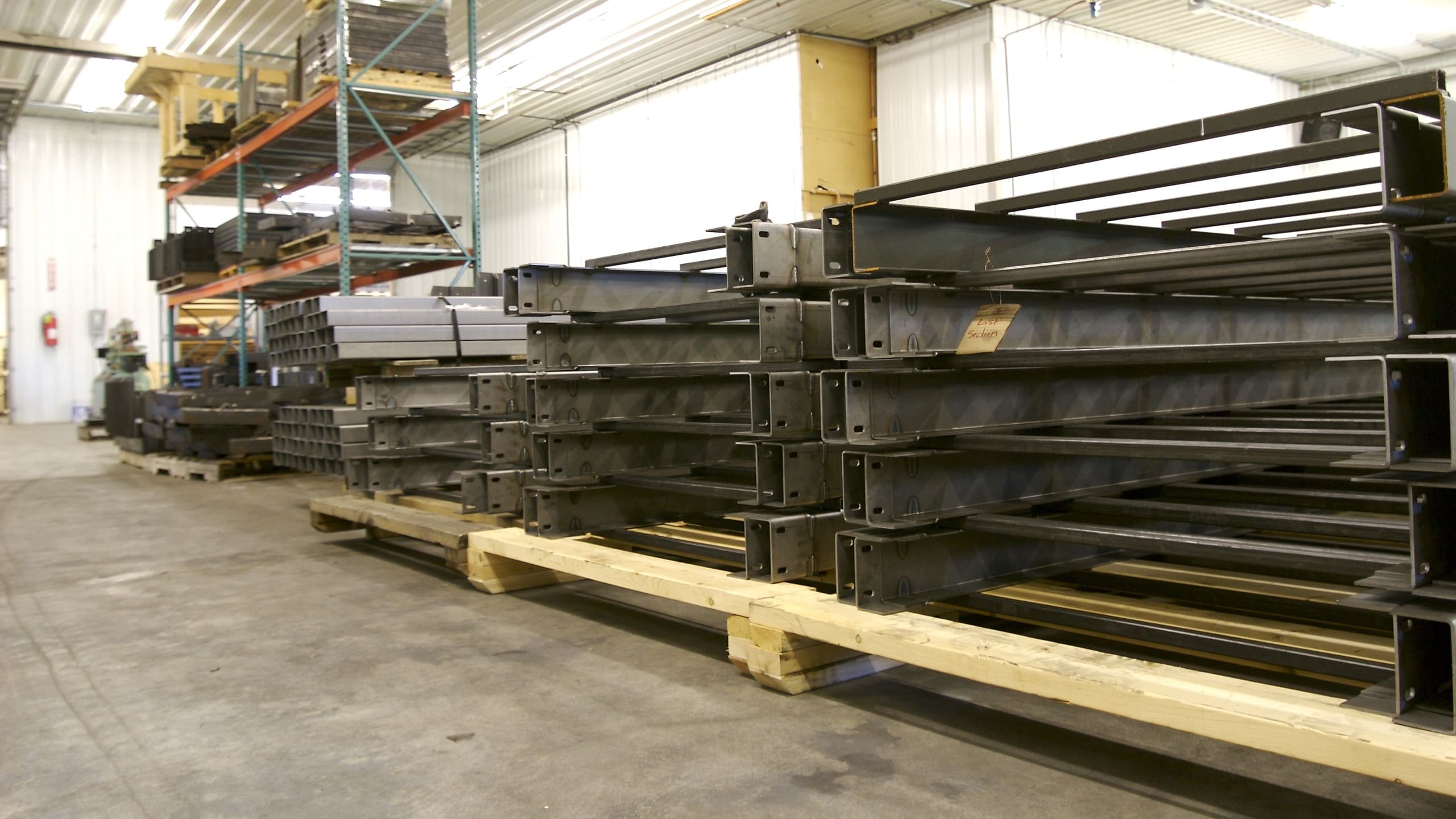
Fabrication & Material Finish
Fabrication & Material Finish
- High Grade Materials Ordered
- Metal Fabrication
- Exterior Rated Coating/Finish
PHASE FOUR
Assembly, QC & Shipping
Assembly, QC & Shipping
- Steel & Electrical Components Assembled
- Quality Control Testing
- Packaging and Shipping
PHASE FIVE
Installation
Installation
- Foundation (typically by others prior to elevator install)
- Supports and Track Installed
- Chassis, Car, Motor and Gear Box Mounted
- Electrical Wiring and Final Setup
PHASE SIX
Quality Assurance & Closeout
Quality Assurance & Closeout
- QC Testing
- Customer Closeout
- Landings Built (by others)
- Permit Inspections (as needed)
- Plan Routine Maintenance
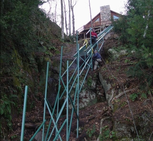
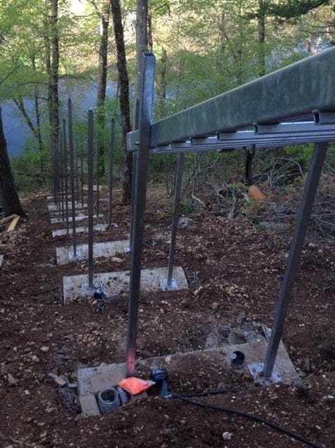
A Deeper Look: Strong Foundation
One of the most important components of every outdoor inclined elevator is its foundation. The process of determining, designing and installing the proper foundation type for each hill’s unique features and soil conditions is critical to the strength, longevity and safety of the whole system. Hill Hiker, Inc. is one of the only companies that offers a full range of foundation options to best meet the challenges of any hillside.
Hydraulic Piles
Buried Posts
Step Footings
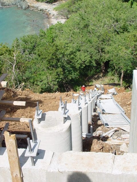
Columns
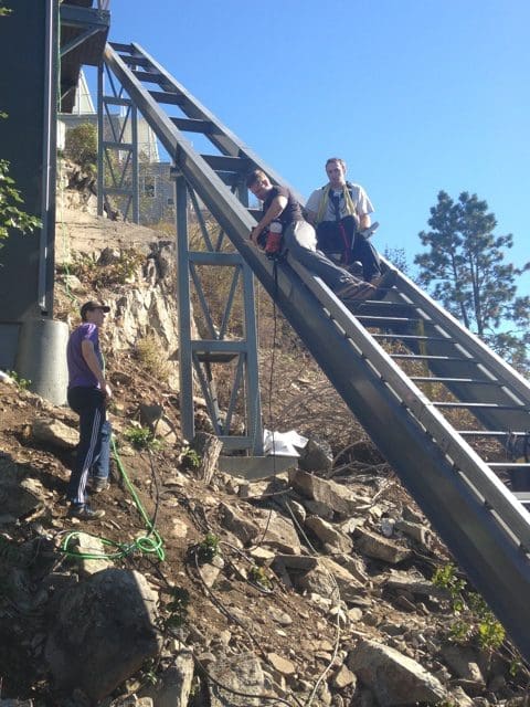
I-Beams
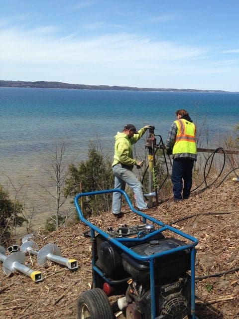
Helical Screws
Pre-Construction
Initial Contact and Site Visit
- Measure hill, determine incline of hillside
- Examine terrain, sample soils
Exact Location of System Determined
- Traffic flow to and from system
- Preservation of trees and vegetation
- Aesthetics and blending with landscape
Determine Custom System Needs
- Foundation requirements based on soils and site
- Size of system based on desired capacity
- Application type – residential vs. commercial
- Local building code requirements
- Customer desired options
Quote and Contract
- Prepare and present finial price and quote
- Reach agreement and sign contract
Contact Local Code Officials
- Begin permitting process
Collaborate and Plan Project
- Work with owner and/or architects and engineers as needed
- Setup Sub-Contractors as needed
- Schedule Pre-Construction meetings as needed
Develop Custom Order
- Create Engineering Drawings
- Place custom order for manufacturing
Manufacturing
Materials Ordered
- High grade standard steel, 304 or 316 stainless steel
- Custom mechanical parts
- Motor, gearbox, drum and electronics package
Custom Fabricate
- Hill Hiker® lift system built to desired specifications
- In house Capabilities – Sheet metal cutting, bending and shearing saves cost
- Precision Welding – Hill Hiker® shop technicians take pride in their craft
High Grade Finish
- Hill Hiker® lift system sent to receive high-grade powder coat paint and/or galvanization
Certified Electronics
- Hill Hiker® lift system electronic package built by qualified (UL) and licensed box shop
Components Assembled
- Hill Hiker® lift system components (car, chassis, motor & gearbox) assembled
Quality Control
- In-house inspection and testing performed
Shipping
- Entire system packaged for shipping
- Tram system sent via third party shipper or delivered by Hill Hiker® crew depending on location
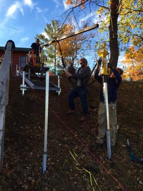
Installation
Site work
- Clear hillside path for lift system
- Layout system location and footings
- Dig footings, motor and gearbox pad (as applicable)
Foundation
- Pour concrete posts or column footings
- Pour motor gearbox pad (as applicable)
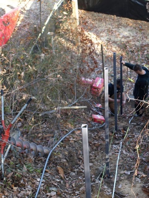
Steel Structure
- Install column brackets or steel posts
- Hang/Install steel rails
- Cross brace posts as need for extra strength
Mechanical
- Place and secure motor and gearbox assembly
- Mount chassis and car
- Install cable
Electrical
- Hook up controller to power
- Wire and set limit switches
- Mount wireless communication
- Test safeties and controls
Landings
- Exit / Entry platforms at each landing station built by Others
- Railings and gates installed on each station by Others
Finalization
- State elevator inspection and permit closeout
- Closeout with owner – instructions and manuals
Frequently Asked Questions
Installation Process
Most likely, yes. We are truly a small, family company serving the world. From hard to reach places like a remote island with 40 foot tides to urban environments, our team can bring our systems to your country or state. Here’s a map detailing our past projects. Don’t see your area on the map? Don’t fret. Our team is always looking to expand to new places.
If your project is in North America, Central America, The Caribbean, Australia or New Zealand, we already have experience and units installed in your area. If your project is in the EU, we are currently in the process of obtaining the necessary CE product certification marks to begin offering our funicular trams and lifts in your area. If you’re anywhere else in the World, let’s talk, we would love to learn more about your project and see what we can do for you.
Possibly, but if not we’ve still got you covered. We use a mix of fully self-reliant dealers as well as local partners for specific stages of the project process along with our factory certified crews of traveling technicians that can go just about anywhere in the world. Check out our dealer page to learn more.
If you are interested in becoming a dealer or partner in one or all of our key business areas such as: design, sales, permitting, installation or service, we would love to hear from you. Contact us here.
The installation process involves three stages: pre-construction, manufacturing and installation. For a complete roadmap of the process, check out our project processes page. It gives a detailed and easy-to-read picture of how your system goes from concept to moving up and down a slope on your property.
Hill Hiker®’s portion of the install takes about 1-2 week for most projects.
Project Phases:
– Pre-construction: design, engineering, permitting, planning
– Manufacturing: ordering, fabrication, material finish, assembly, QC, shipping
– Installation: clearing, foundation, system install, landings, inspection, close out
The entire project duration from start (down payment) to finish (inspection) can vary greatly and depends on many factors such as the complexity of the system, material ordering lead times, the level of engineering, permitting and inspection needed, the foundation and landings type, shipping, etc. Because many of these tasks are out of Hill Hiker®’s control, it can be very hard to give accurate and complete timelines. If you want to learn more about the project process, check out our Manufacturing and Installation Process page or contact us.